by Loïc
Forewords
 For some time, I have done several attempts to build a pop-pop coil made of glass
Following some disappointments, Jean-Yves suggested to me to use a test tube, with a plug and a thinner tube for the outlet pipe. I waited long before starting that job and, some days ago, we were informed of the assembly done by Jorge Hugo Cordero which is totally in accordance with what we intended to do. Thus stitched (!), I decided to start, and I propose you to see how. For some time, I have done several attempts to build a pop-pop coil made of glass
Following some disappointments, Jean-Yves suggested to me to use a test tube, with a plug and a thinner tube for the outlet pipe. I waited long before starting that job and, some days ago, we were informed of the assembly done by Jorge Hugo Cordero which is totally in accordance with what we intended to do. Thus stitched (!), I decided to start, and I propose you to see how.
Where we start step one !
Assembling
Nothing, really nothing is complicated for the mounting. The parts being available, in less than 3 minutes it is finished, 5 if we add the time needed to strike a match !
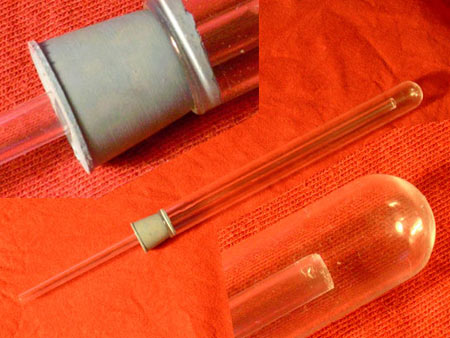
A picture being better than a long speech
The pipe we used is 160 mm long, with external diameter 16 mm and internal one 13 mm. We can add that it is a classic test tube made of Pyrex (=borosilicated glass) used in laboratories. The plug is made of rubber. The thin pipe (6 ext, 3.5 int) is a pipette made of Pyrex. It has been cut at an appropriate length and the graduations have been removed by scratching.
If you are many to be interested, I can arrange for a global order and then I can dispatch according to every one needs
I wait for your e.mails on this matter.
Starting
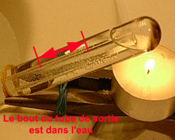
A dish warming candle suits perfectly. In practice, the tube will not visibly blacken.
The starting time is relatively long. It is understandable if we consider the big volume of water, even though the whole water is not heated up to 100°C (luckily!). Then, as we observed with the glass coil, an oscillation takes place in the outlet pipe.
Here is a picture of the "boiler" while running. To see more, you can load a video sequence .
Intermediate conclusion
Hence, we are looking at a pop-pop engine which works, and which delivers a thrust very likely sufficient to propel a small float
but having an heavy weight due to the useless big amount of water
Therefore, to solve this problem, let's cut the tube!
Where we start step 2
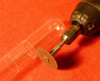
Tube cutting To cut the tube, it must be grooved. As the steel tool that I had got refuses to streak the glass, and as I had no quartz (or diamond!) available, I used a mini grinding disk (corindon) mounted on a Dremel.
To be sure that the end and the beginning of the groove will meet, I followed one side of an adhesive tape
Once this is done, the best is to heat locally with a little candle the grooved area, and to put it under cold water
thus the glass cracks and it suffices to exert a slight pull to split both ends. (Hum
as you have to learn before being an expert, forecast some spare parts
To get 2 good parts, I killed 4
)
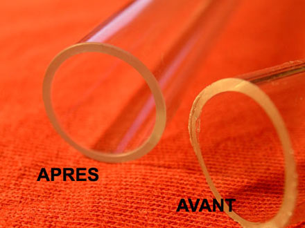
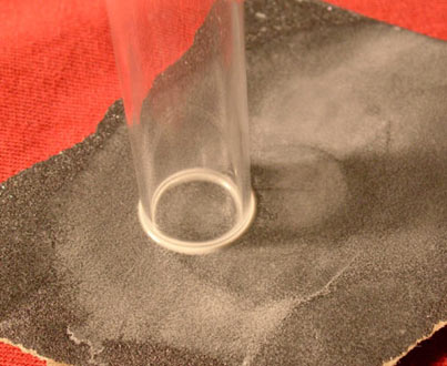
A (very hot) flame to do the glass end melts a little, and thus becomes rounded is wished, in order to cancel any longitudinal crack. Another possible alternative could be to use a sheet of sand paper as there is for car body works (dark grey, grade 180 to 400), taking care of working with some water
It is long, but very efficient to ensure a good finish of the edge
Assembly n°2
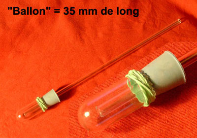
The tube is now no more than 35 mm long. The rubber bracelet that can be seen on the picture at the bottom of the boiler was there to prevent the enlarging of a crack (detected when the plug has been inserted
).
Starting n°2
Starting is now quicker. During the first test, the oscillating area was located near the plug, and it was difficult to see
A more powerful flame allowed to get a bigger volume of gas, and thus to move the oscillating area after the plug. One could also cut the plug to narrow the shadow area
.
As we performed the tests, there was always some water on the rubber plug, allowing it not to burn (!).
The oscillating stroke is longer (x1.5 to 2) than the one we got with the full length tube. It is difficult to ensure that the shortening is responsible of that, because other parameters (flame, distance from test tube bottom to the pipe inlet, immersion depth of the pipe outlet in the tank) are not accurately monitored. However, a cause and effect relationship could exist (we will revert on that later).
Finally, let's say that the jolts of the pulsed jet are well detected when fingers are set at the pipe outlet... ("strong" blow) as I detected a "strong" suction force was when trying to close the pipe with a finger (subjective, I agree with you !).
Where we conclude for this page
It looks like we are facing a very easy means to study pop-pop engines. In addition, it occurs that it could be the easiest way to build a pop-pop engine, insofar as the components, easy to find (if not, ask for some help), are all available.
Other comments will follow to analyse the various results but at this stage it is already possible to express some thoughts :
- An unwished air ingress by the bottom of the pipe allowed us to see that it doesn't disturb too much the working. Indeed, this one is very soon restored (air ingress => oscillating interface more far from the drum, then, the oscillating interface climbs up, without reaching the level that was seen before the air ingress).
- Due to a big air ingress, the oscillating interface climbed down to 150mm
the oscillation goes on for 10 more seconds, before stopping
It restarted when the candle was slightly shifted in order to vaporize some remaining liquid water
In this test, it is obvious that the zone of the pipe where the interface was evolving during 10 seconds was not at all able to vaporize water because it was cold. The elasticity effect of the steam is therefore very important
more than I thought when I wrote that the water is, in permanent conditions, thrown out because of a flashing (see "Touring the system").
See you soon for other experiments on this matter, and
let us know your own experiments !
« Back to "Pop-pop"
|